Admins, I can’t post in guides so please move this to guides if it meets standards.
This is a guide to show how to create a simple latch and a counter. Then how to combine them to create a timer.
If none of that sounds interesting, trust me, digital circuit stuff (real or fake) is all about building a “library” of smaller designs, then figuring out how and when to use them.
This guide won’t cover input or output components, honestly input/output is what’s limiting circuits right now. I hope that by showing people what even basic logic gates can do, it’ll encourage devs to port some input/output components from /TG/
If you want to just see the designs please scroll to the bottom, if you want to understand what they’re doing read on.
Logic Gates and Truth Tables
The fundamental building block of all digital circuits and computers. Logic gates take inputs, and spit out outputs according to some rule.
Truth Tables are the written out example of this.
Ie. For an AND gate.

| A | B | O|
| 0 | 0 | 0 |
| 1 | 0 | 0 |
| 0 | 1 | 0 |
| 1 | 1 | 1 |
This means that only that last case of having A =1 AND B=1 will output a true.
Truth tables are incredibly useful and you can create them quite easily, or look them up.
You should try to understand and/or memorize the tables for AND, OR, and XOR
Note, that once you wire multiple gates together, you may have to create a truth table for your entire creation to help understand what it does.
States and triggers
So gates are cool and all but something has to trigger them.
In the real world gates start reacting the moment their inputs change. Here however, they are triggered.
The most common triggers you’ll use are the Clock, and a button. They send out pulses which will cause a component to do it’s job. IE an AND gate will not AND the inputs until it’s been triggered.
The clock component allows for your creation to keep going after you stop pressing the button. It’s important to think of clocks as having cycles, and in each cycle everything happens, then next cycle, it all happens again. This doesn’t have to be strictly true I don’t think, but start out with that assumption and learn where to bend the rules later is my opinion.
The button is for when you wanna initiate the event, or if you want to change what’s happening. This will become more obvious later when we use a button to stop a counter.
States are nastier. When a system acquires a state, everything gets more complicated. Luckily it’s pretty easy to know if you need a state. Basically, does it need to remember previous iterations?
Consider a roulette wheel vs a bingo ball dispenser. The roulette wheel doesn’t need to know previous spins to calculate it’s next spin. It’s just random. A bingo ball dispenser, however, has to keep track of what balls it’s dispensed. A physical one does this by physically sending the ball out. A digital one has to remember what was randomly rolled previously.
States will mostly be stored in RAM, but you could 100% create your own memory component out of just gates, so have fun. Fun fact, all logic gates, and thus digital devices, can be created using just NAND gates, which is an AND gate connected to a NOT gate.
States mean the inputs to gates will change, meaning you have to consider more rows of the truth table. Increasing difficulty and complexity.
A latch circuit
A latch circuit’s job is to hold a previous value, with the option to clear this latch. Below is a simple toggle latch.
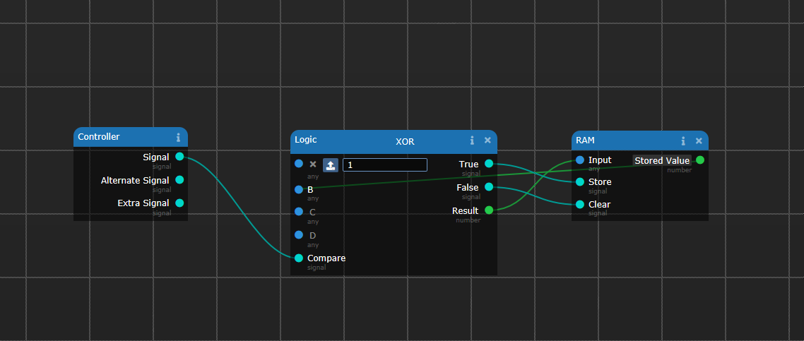
To analyze it, first we see an XOR there, so let’s draw a table for it:
XOR is “Exclusive OR”, meaning that it will be true ONLY when both inputs are not the same.
In single bit binary, that means 1-1 or 0-0 will result in a 0 out.
| A | B | O|
| 0 | 0 | 0 |
| 1 | 0 | 1 |
| 0 | 1 | 1 |
| 1 | 1 | 0 |
So the A input is hard coded to be a 1. This means we can ignore all rows that have A=0.
So that leaves us with just B = 0 therefore O = 1. Or B = 1, and O = 0
It is essentially a NOT gate at this point. But you can make it from a Logic component.
The RAM component will initialize Null, which will feed back a 0 to the xor gate’s B node.
So, on the first press, look at the second row in the truth table. O = 1 so the XOR will trigger True, and set result = 1.
The signal sent from “True” to “Store” will cause the ram to store the 1 being sent from result.
“Stored Value” will now be stable at 1. It is also being looped back to B as you can see.
On the next button press, A = 1, but now B = 1. Meaning the XOR will trigger False and set result to 0. Triggering clear will set the output to null again. (Note, if you want output to reset to 0, then simply wire false up to store as well.) At this point, the looped back value to B will be 0 again. Meaning we’ve reached a previous state. A = 1, B = 0. The A can’t change, and B can only be 0 or 1 and we’ve seen what happens both times then. Thus this circuit can only ever toggle between 0 and 1.
Note you can clear the latch via any method. It doesn’t have to be a toggle.
Counter
Next is a counter. A counter counts up.
Question? Should a counter have a state?

Answer: Yes, it has to, how else can it remember what number it just had.
Go ahead and try to count without remembering your last number.
I’m using a clock here, but any pulse will work, it depends on what you want to count. Button presses? Time? number of deaths on station? Here we’re building a timer circuit, so it’s based on a clock. You can think of the clock as in game way to use “time has passed” as a repeatable input.
There’s no gates here, so no truth table, but it’s worth understanding Arithmetic components.
Every time the clock pulses, 1 will be added to B. Initially “Stored Value” on the ram will be Null so B = Null = 0 so “output” will be a 1 after the first pulse. This value is stored in ram and fed back, causing the next pulse to add to B =1, then B=2 and so on counting up.
I think it’s important to use ram here since the ram won’t update when the arithmetic component is triggered guaranteeing it won’t change while the arithmetic happens. I think it’s probably fine in the game, but direct feedback feels wrong to me and seems like it could go wonky. It also gives you a reset option by pulsing the clear signal on the ram.
You should use the arithmetic output directly, and not the RAM, since the ram doesn’t have a trigger output. The RAM exists just to hold the previous iteration’s number.
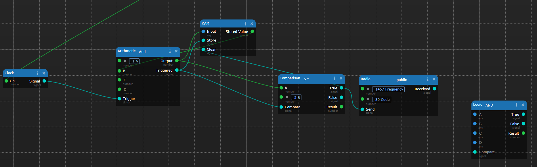
Here we add a comparer to our counter, when the counter goes above the set target number of cycles. Once you reach that number, you’ll get a radio signal sent. It will also clear the counter so it can start counting all over again.
Note, you can use one of the other buttons on the shell, create a list of speeds, then use a button connected to a counter, to count up and index the speed, then reset the count at the end. Or you could toy with multiplexers if you’re brave.
That’s enough for now though. Good luck and ignore that logic thing on the right. The station was on fire when I took the picture.