It is 2 part design. It is really simple one too, I made it while experimenting. I am sharing it, so it can be shown how it works and so it can be experimented with by you people. I’d recommend experimenting with it yourself, i do not have much experience with circuits, so it may be a bit underwhelming but it was fun to make this. I hope it will give you some ideas or some base on which you can make your own Pilot steered mobile circuit.
Designs Require Advanced Circuits to be printed.
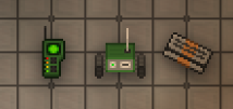
RC Car.
{"assembly":{"type":"type-a electronic drone","name":"RC Car","desc":"Simple Design RC Car. Use Data Card to Sync to Pilot.","detail_color":"#44843C"},"components":[{"type":"NTNet networking circuit","inputs":[[1,0,"934815ad"]]},{"type":"data card reader","inputs":[[1,0,"RC Car NTNet ID"],[2,0,"2bcab9d9"],[3,0,1]]},{"type":"local locator"},{"type":"NTNet scanner"},{"type":"reference decoder","inputs":[[1,0,"0e6337626669666e676518"]]},{"type":"examiner"},{"type":"not equal gate","inputs":[[1,0,1],[2,0,0]]},{"type":"coordinate pathfinder","inputs":[[1,0,172],[2,0,119]]},{"type":"locomotion circuit","inputs":[[1,0,2]]},{"type":"custom ticker","inputs":[[1,0,1],[2,0,10]]},{"type":"advanced rel to abs coordinate converter","inputs":[[1,0,0],[2,0,-1]]},{"type":"tesla power relay"},{"type":"tiny photovoltaic cell"},{"type":"starter"}],"wires":[[[1,"I",1],[1,"O",4]],[[1,"O",2],[5,"I",1]],[[1,"A",2],[5,"A",1]],[[2,"I",2],[4,"O",1]],[[3,"O",1],[4,"I",1]],[[3,"A",1],[14,"A",1]],[[3,"A",2],[4,"A",1]],[[5,"O",1],[6,"I",1]],[[5,"A",2],[6,"A",1]],[[6,"O",3],[11,"I",1]],[[6,"O",4],[11,"I",2]],[[6,"A",1],[8,"A",2]],[[6,"A",2],[7,"A",1]],[[6,"A",2],[11,"A",1]],[[7,"O",1],[10,"I",1]],[[7,"A",1],[10,"A",1]],[[7,"A",2],[8,"A",1]],[[8,"I",1],[11,"O",1]],[[8,"I",2],[11,"O",2]],[[8,"O",1],[9,"I",1]],[[8,"A",2],[9,"A",1]]]}
Pilot
{"assembly":{"type":"type-d electronic assembly","name":"RC Car Pilot","desc":"Used to Steer RC Car. Use Data Card to Sync to RC Car.","detail_color":"#44843C"},"components":[{"type":"NTNet networking circuit","inputs":[[1,0,"2bcab9d9"],[2,0,"0e6337626669666e676518"],[4,0,"934815ad"]]},{"type":"ranged sensor"},{"type":"reference encoder"},{"type":"local locator"},{"type":"NTNet scanner"},{"type":"data card reader"},{"type":"tiny photovoltaic cell"},{"type":"starter"}],"wires":[[[1,"I",1],[6,"O",2]],[[1,"I",2],[3,"O",1]],[[1,"I",4],[5,"O",1]],[[1,"A",1],[3,"A",2]],[[2,"O",1],[3,"I",1]],[[2,"A",1],[3,"A",1]],[[4,"O",1],[5,"I",1]],[[4,"A",1],[8,"A",1]],[[4,"A",2],[5,"A",1]]]}
You must use Data Card on the RC Car First, then on the Pilot.
Edit: I added starter, so it updates the NTScanner inside of the machine by itself.