This guide will show you the basics behind Wiremod Circuits, how to read them, and some basic starter circuit chunks that can be combined with others to make complex circuits. This guide covers Wiremod circuits as of October 2023.
What’s In A Circuit?
A circuit needs 5 elements to be a “functional circuit”. You can get almost all of them from the Component Printer, located in Research and Development.
These items are:
- Shell: This is what contains your circuit. Ranges from robots to airlocks and brain implants.
- Integrated Circuit: What you actually build the circuit on and what controls the logic.
- Cell: A battery to power your circuit. Larger cells are better, as circuits can be quite power hungry.
- Inputs: Triggers to activate your circuit to do something.
- Outputs: The “Do Something” of your circuits.
Building a circuit involves just a few steps.
- Get a charged cell, and attach it to the integrated circuit by clicking on it.
- Finish your shell if needed. For instance, server shells and robot shells need to be screwdrivered first. Servers also need to be anchored to work for the first time (This is probably a bug, so just keep them anchored).
- Insert your circuit into your shell.
- Insert any components directly into the shell.
- Print a Circuit Multitool, and use it on the shell to open the circuit directly. You may have to click twice (once “marks” the shell, the second will open the circuit interface).
- Wire up your inputs, outputs and other components by click dragging from the nodes. Right click on a node to delete bad wires.
- Trigger your circuit and marvel as it… fails to work the first time…
- Fix it, and marvel as it… might work the way you expect. Repeat until it actually works.
Getting into the Flow State
Circuits work by the flow of information. Inputs generate triggers, which flow to other components, which trigger more outputs. Let’s look at the most basic circuit, the Clown’s Bike Horn Replacement. Print out a compact remote, integrated circuit, a power cell (and charge it), and a Sound Emitter. Assemble your circuit, and wire it like the following image. You can name the circuit, by typing in the name box in the top left. If you insert the circuit, and it doesn’t work, use your circuit multitool to edit the circuit in place.
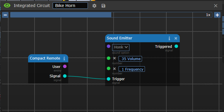
Once the circuit is complete, you should be able to activate the remote in hand, and get a honk out of the circuit. This is because when you push the button, the “Compact Remote” object outputs you as the user output, and a “Signal” that you pushed it.
The cyan wires are a special datatype: A Signal. Usually, these Signals trigger the next element in your circuit. If you dig into the code, you’ll find out that a signal is just the world timestamp of when the signal was output. The flow of these signals determines the operating order of your circuit. If signals don’t trigger in the right order, your circuit may be working with old data. For the most part, you should attempt to flow signals in one continuous path from left to right, but there are times when you can branch the signals to get slightly faster execution. I’ll describe more about that later.
As components get triggered, they process their internal state, and will emit a signal to trigger the next component.
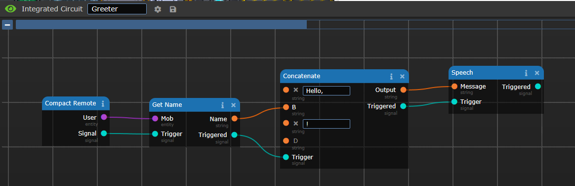
When you push the button on this remote, it passes the Mob that activated the button to the “Get Name” component. This component gets the name of the mob as a string of letters, and passes it to the concatenate object. The signal causes the concatenate component to trigger, combining the strings: "Hello, ", the name, and “!” into “Hello, Central Command!”, and passes it to the speech component, which says the full string.
![]()
Achieving flow state with circuits is very similar to the process of understanding Atmospherics Piping: Stare at it until it makes sense. Start at the left side of the circuit, and find your inputs. Trace the signals, and figure out what components do what. Reading aloud the Greeter circuit would be something like this:
- When someone pushes the button on the compact remote…
- The circuit figures out the name of the mob that pushed the button…
- and combines it with "Hello, ", and “!”, to form another string…
- and then speaks it.
If we modify the circuit a little bit…
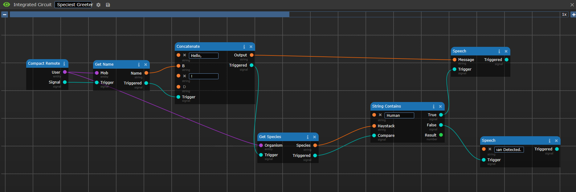
Reading this circuit:
- When someone pushes the button…
- Get the name of the mob…
- Make a string with "Hello, ", the name, and “!”…
- Then get the species of the mob…
- Then see if “human” is found in the string of the mob that triggered the remote…
- If it is, speak the full string, otherwise…
- If not, speak “Non-Human Detected!”
We can detect humans…
![]()
or non-humans.
![]()
For the most part, a lot of circuits can be simplified by following the signals along the path. Usually, the data flows directly in parallel, so you can figure out the circuit’s purpose by tracing the conversion of the data from input to output.
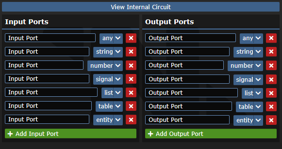
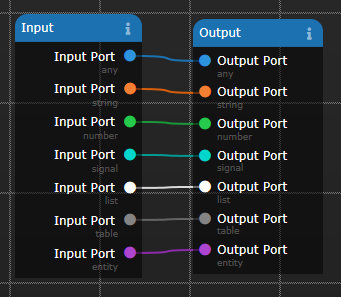
Data Types
With circuits, the color of the wire determines what the output is trying to send. Some types can be cross connected, and will automatically be converted (or cast) into the correct type for the input. For instance, wiring a number output into a string input will cause the number to be converted to a string. If the output won’t connect to the input, the types can’t be automatically converted, so you are missing a step.
These are the most common datatypes that you will see in a circuit. Each has different properties, and differerent components to modify them.
- Cyan: Signals: Trigger Components to do things, controlling the circuit operation.
- Orange: Strings: Text. “Hello!”, “Activating”, “Stealing the Clown’s shoes…”, are all strings.
- Green: Numbers
- Purple: Options
- White: Lists: A group of entities that has a numerical index. For instance, a list of strings could be: 1: “Medbay”, 2: “Brig”, 3: “Science”. The index starts at 1 and goes up to the maximum number of objects in the list. Use the Index Component to access specific objects in the list.
- Grey: Table: A special list, which has columns instead of indices. A Crew Monitoring console outputs a table that has the “name”, “job”, and other parameters, which can be searched. It’s a fancy list.
- Pink: Objects or Entities
- Blue: Any. This will take any of the previous types… but may do weird things if you mix datatypes in components.
Common Circuit Elements
These next few sections are going to explain what some of the common elements that you’ll be using to make your circuits. For the most part, they are labelled what they do, but there are some exceptions. I’m listing all of the shells (because they each do special things), and most of the common components that you will use regularly.
Shells
Simple Shells
- Compact Remote: It has one button, and returns who used it.
- Controller: Has “3” Buttons. First button is just activate in hand, second is alt-click. The third button is a lie. You need to right click it… which opens the context menu.
- Modular Assembly: Like a customizable remote signaller. Can pulse or detect pulses from attached devices. Fits in pockets!
- Bot Shell: It has one button and USB ports, but can’t be picked up.
- Server: A large shell that can be anchored. Has USB ports, but that’s about it.
- Brain-Computer Interface: A circuit that can be implanted in your mind! By default comes with 3 buttons, but can be augmented with thought listeners, more buttons or target interceptors. Note: As of Oct 2023, the overlays are all broken. Don’t use them or you will be stuck with them in your field of view permanently (as far as I can tell).
Specialty Shells
- Circuit Airlock Assembly: An airlock, but without the normal access circuitry. Has an event, which fires when an entity bumps into it to open it, and bolt, unbolt, open and close outputs.
- Drone Shell: A simple robot that can move! Has 4 outputs for movement, and can be equipped with a pull component to pull objects.
- Money Bot: An ATM-like shell. Takes money from users, and can dispense money (if it has it in the till). Can be locked with an ID to prevent theft.
- Scanner: Returns Scanned items as an input.
- Scanner Gate: Like a scanner, but scans whatever object enters the same tile.
Inputs
- Voice Activator: This is a microphone, which outputs the speaker of any noises nearby and the message. Use with “String Contains” to get passwords, “Get Species” or “Get Name” to make racist / personal doors.
- GPS: Behaves like a GPS unit, outputs your coordinates on the map. Critical for teleporter shenanigans.
- Radio Component: Receives signaller pulses. Simpler than using NTNet, but can only do signals.
- NTNet Receiver: A powerful radio system allowing you to send data between circuits. Commonly used to remote control a Bluespace Launchpad using a BCI.
- Health Component: Reports health of an entity. Can be updated using the “mark” function of a circuit multitool.
- MMI Interface: A theoretically cool idea, but potentially extremely lame for the player trapped in a circuit. Allows you to install MMIs into circuitry to cause them to trigger things. Make sure your circuits work and the other player consents before trapping another person inside a circuit which doesn’t work.
- Clock Input: Triggers every 0.9 seconds. I’d use a different method (detailed later) if you want a repeating update.
Outputs
- Speech: Causes the circuit to talk. Very useful for debugging, because you can pass basically anything into it and it will figure out how to speak it.
- Light Component: Does what it says on the box. Makes your circuit glow. Includes fancy RGB lighting.
- NTNet Transmitter: The other end of the NTNet Receiver. Used to send information to receivers.
- Radio: Can also be used to send signals, as well as receive.
- Sound Emitter: Be more annoying than the clown by spamming Honks everywhere. Can’t beep, but can Ping, Chime and Buzz. Includes bonus Sarcasm Mode: Sad Trombone and Slow Clap Modules.
Components
These components are most of what you will be messing with. A lot of the others are implemented because they exist on a programming language level, but are not too useful in the types of circuits which are useful in game.
- Arithmetic Component: Does Math (add, subtract, multiply, divide, etc)
- Comparison Component: Compares multiple signals and outputs a true or false signal.
- String Contains: Searches a “haystack” string, for a “needle” target string. Outputs a true/false signal.
- Delay: Pauses for a certain amount of time.
- Concatenate: Combines Strings
- Length: Gets the size of lists, tables, and strings. Combine with Iterators to step through an entire list.
- Iterator: The “for” part of a for loop. Every time the step input is pulsed, moves the output towards the final value. Combine with Length and Index List to process all elements of a list.
- Index List / Index Table: Gets a specific index from a list or a table.
- USB Cable: Used to connect devices to circuits. Put the circuit in a shell which supports USB ports, then click on the shell with the USB cable and then the object you want to connect. Wired USB cables have a short distance, the Wireless USB Transmitters have a much longer range.
Common Circuits
In this section, I’m going to go over chunks of circuits which can be useful by themselves. I’m not going to go into crazy circuits, but the pieces I will describe can be pretty easily modified into fun circuits.
Advanced Universal Translator
I lied, this is a basic, but very useful, fully complete circuit. This translator will detect non-galactic common languages, and state the speaker and what was said.
Parts List:
- Modular Assembly: I like this because it fits in a pocket.
- Integrated Circuit
- Power Cell
- Voice Activator
- String Contains: This is set to “galactic common” as the needle, but the textbox cuts off.
- Get Name
- Concatenate
- Speech


Brain Based NTNet Speaker
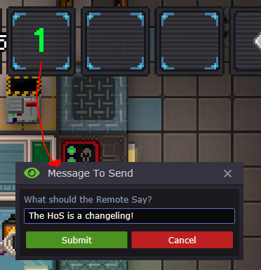
This circuit will send a message to another circuit, so you can send anonymous messages silently. Use a BCI Implanter to implant the transmitter into your brain, and mail the receiver to the bridge. If you need to modify the BCI, jump back in the implanter, and it will extract the BCI. Alt-click the implanter to remove the cell, and then you can use your multitool on it to edit it.
Transmitter:

Receiver:
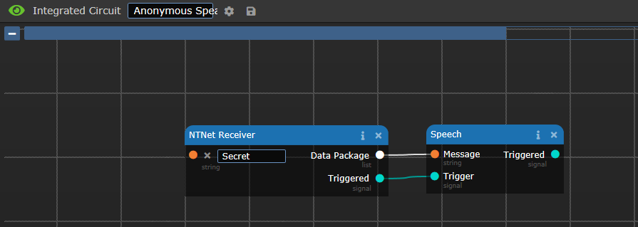
Output:
![]()
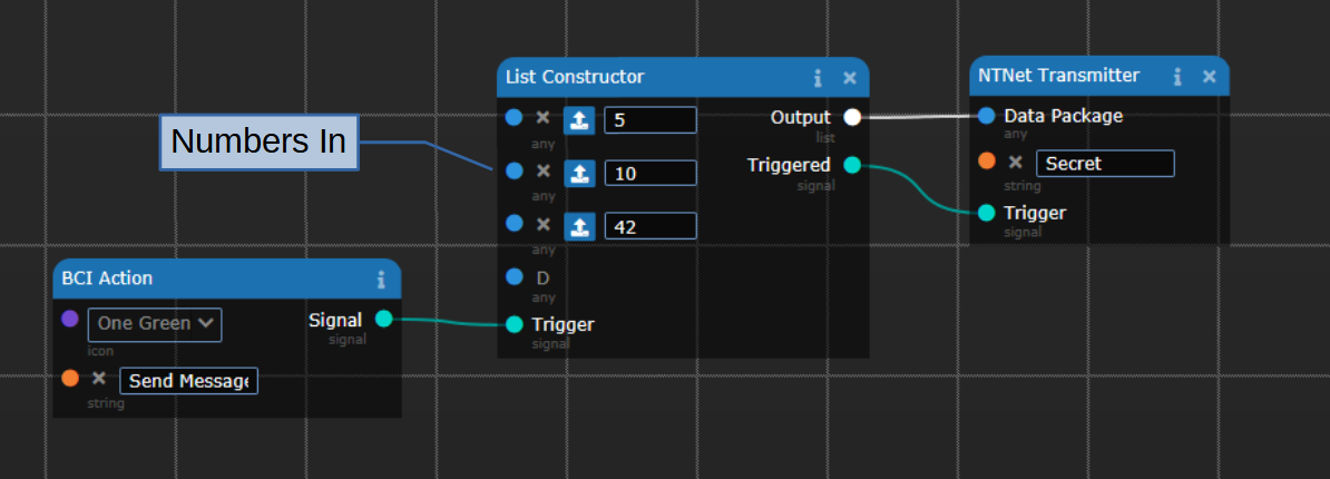
NTNet List Sending
This is the basis for a few different circuits. By using a List Constructor, you can send multiple things through an NTNet Link. This example will send 3 numbers, which will be spoken at the other end.
Transmitter:
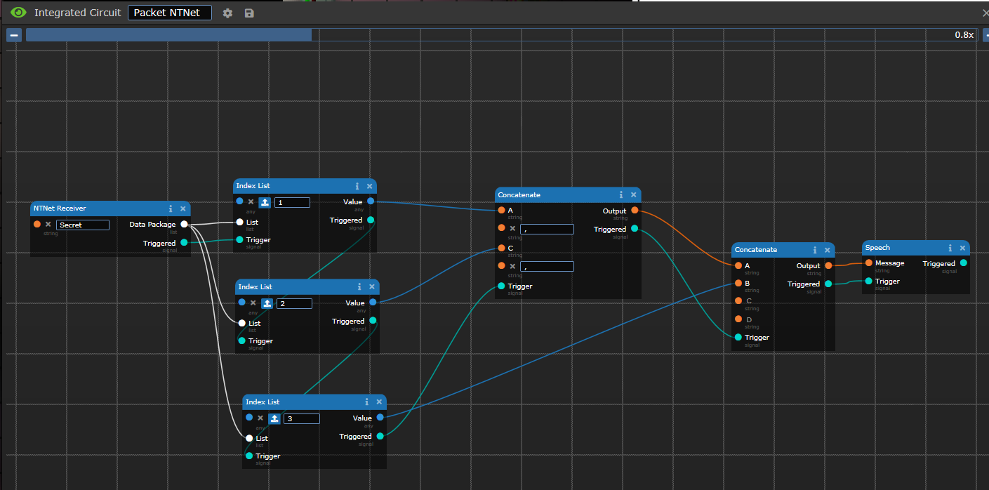
Receiver:
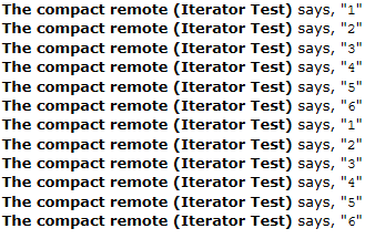
Output:
If you use a List Constructor, you can pass data into the NTNet transmitter, and then pull it apart on the other end with a series of Index List components.
Iterators
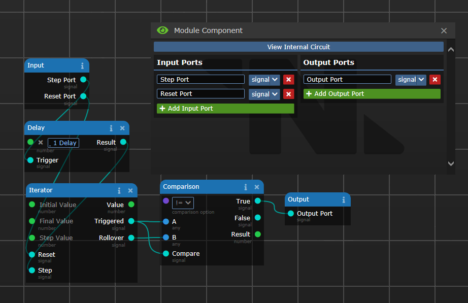
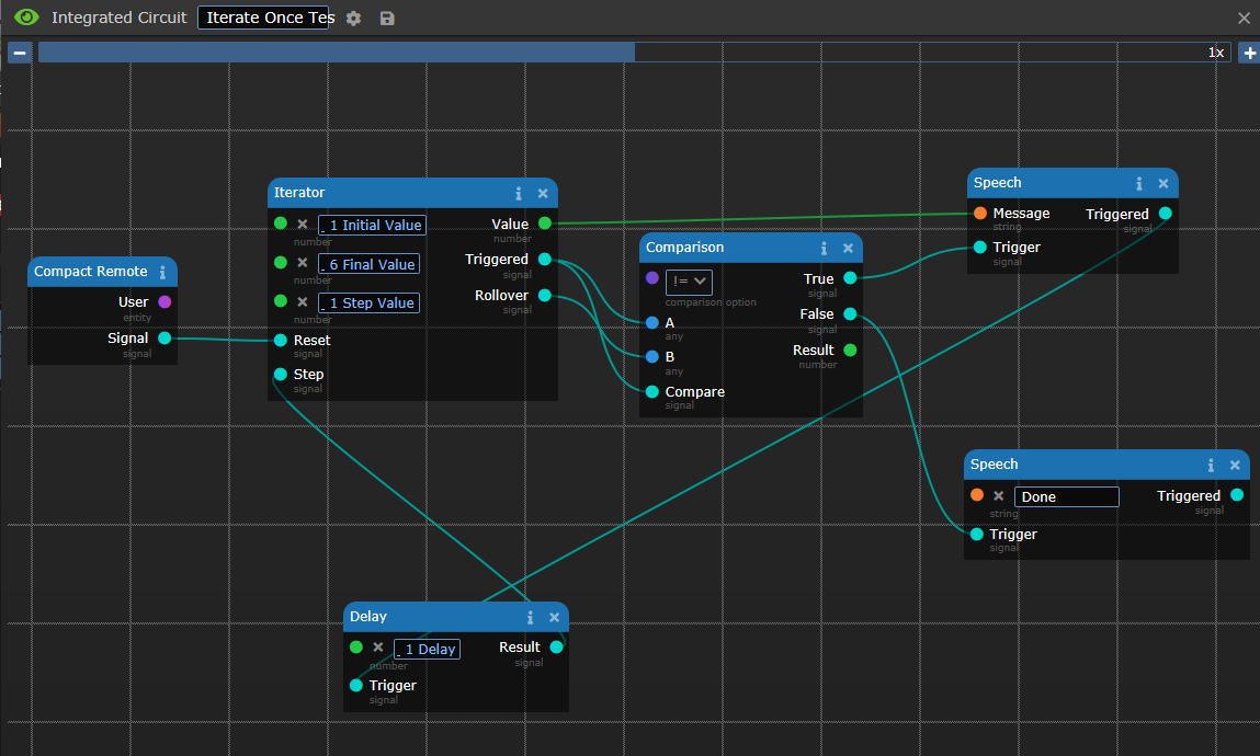
The iterator component is the first line of a for loop. It starts at the initial value, counts up to (and includes) the Final Value by the Step value, and then rolls over. You can use this to iterate through all sorts of things, from potential coordinates, selectable lists (Teleport to: “Bar”, “Medbay”, “Brig”), Suit Sensor Information, etc.

The iterator steps up or down depending on if the final value is larger or smaller than the initial value, and will automatically loop when it gets to the bottom. When it rolls over, it outputs a signal on the rollover output.
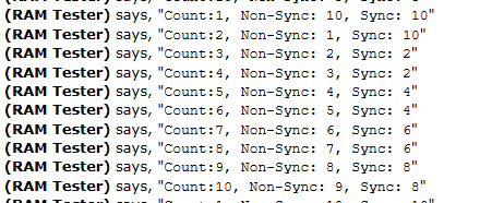
But what if you only want to iterate through a list once? For instance, looping through suit sensors. Well, remember how earlier, I mentioned that Signals are actually just timestamps? If we tie both the Trigger and the Rollover signals to a Not Equal comparison, with the Triggered output also going to the “Trigger Comparison” input, we can stop when we roll over. Every time the iterator steps, the signal for the Triggered output will change, but the rollover will not. Once the rollover occurs, the rollover signal and the trigger signal will have the same timestamp.
If we could start the iterator at time = 10 seconds, the signals would look like this (I’m leaving not updated signals blank, for clarity):
World| Iteration | Triggered | Rollover | Not Equal
Time |           | Signal    | Signal   | Signal
10   | 1         | 10        |          | 10 (True)
11   | 2         | 11        |          | 11 (True)
12   | 3         | 12        |          | 12 (True)
13   | 4         | 13        |          | 13 (True)
14   | 5         | 14        |          | 14 (True)
15   | 6         | 15        |          | 15 (True)
16   | 7         | 16        | 16       | (FALSE)
“If the Triggered Signal Timestamp does not equal the Rollover Signal Timestamp, trigger the next component, as we have not rolled over yet. If the time stamps match, we just rolled over, so say ‘Done’”

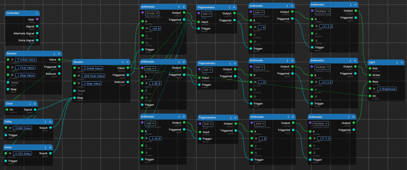
Better Clock Component
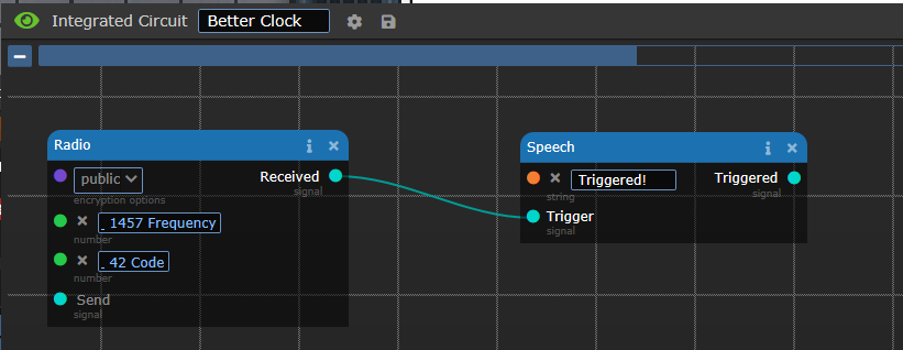
If you want to trigger a circuit at a repeatable time, without the complexity of having to count using a clock and an iterator component, we can combine the powers of two mechanics: The circuits system, and the assembly system.
Grab a Radio Component, and pick a frequency and code. This signal will be sent by the assembly we are about to create. This is the test circuit I am using.
Grab a Timer and a Remote Signaller from Toxins or a lathe. Set your signaller to the same settings that you set in the first step, and set your timer to the time you want the circuit to fire at.
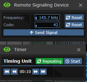
Grab a screwdriver, and click on both the timer and the signaller to ready them for attachment. Click on one with the other to make an assembly of the timer and the signaller.

Open the menu, and push the start button on the timer. After the timer expires, you’ll get a triple beep, and a speech output.
Hide the timer and signaller assembly somewhere if you are annoyed by the beeping.
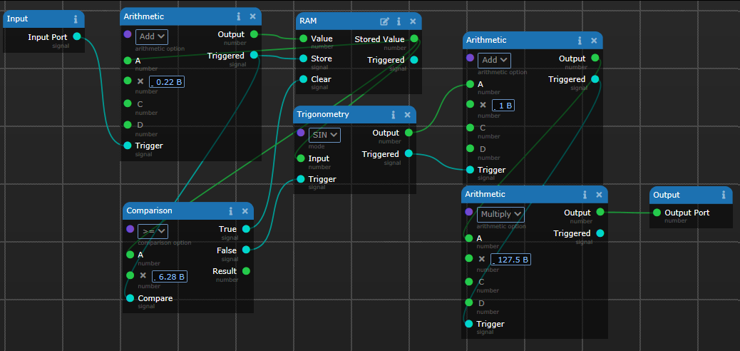
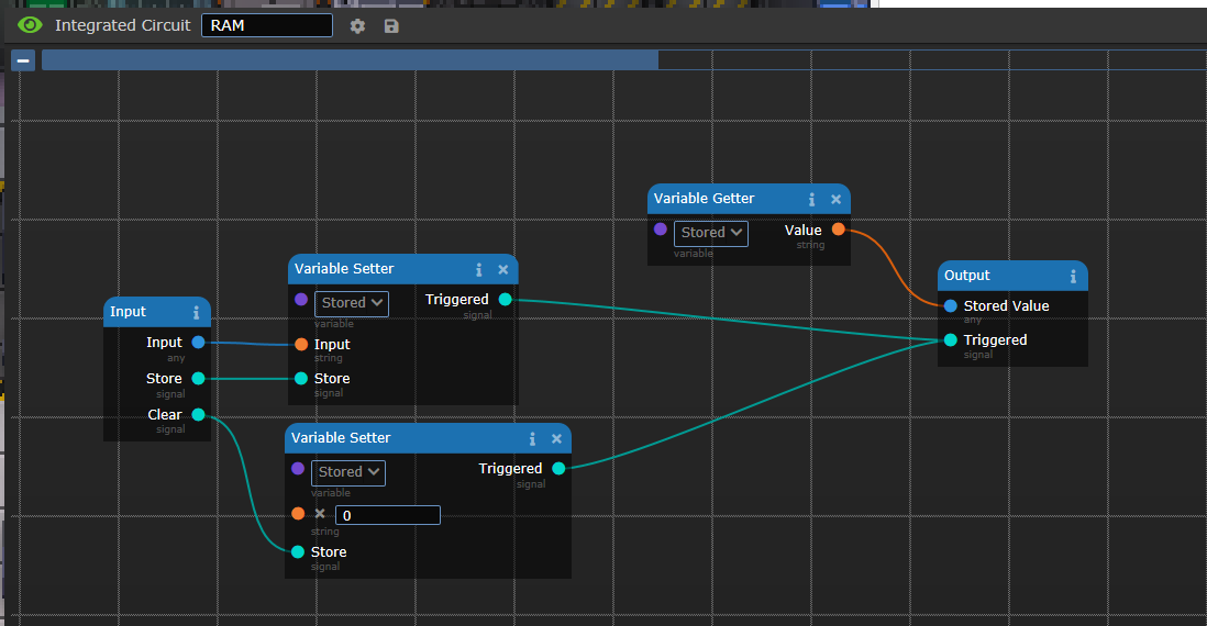
Getters and Setters
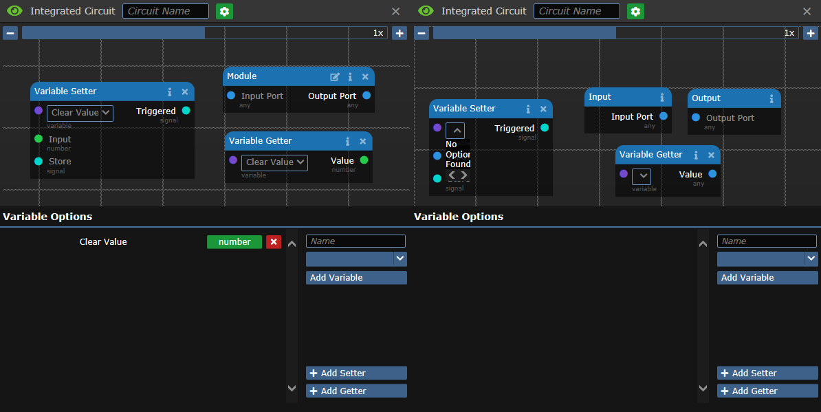
If you have information that you need to store between triggers, you can use a Getter and a Setter. They act as variables for the circuit. By clicking the gear next to the name of the circuit, you can bring up the variable information panel.
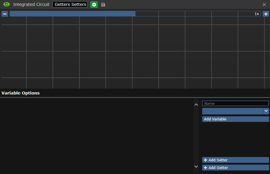
Fill in the type of variable you want to store, and give it a name, and click Add Variable.
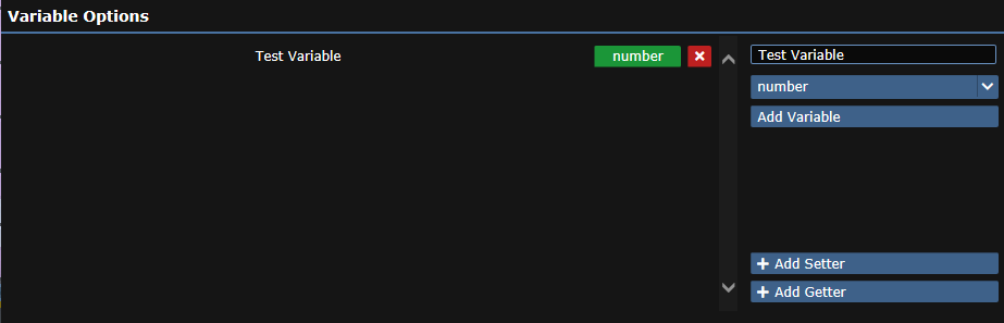
Click the Add Setter and Add Getter buttons to add components to your circuit board which interact with the variable.
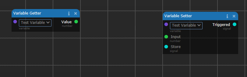
Use the purple dropdown to select your variable name. The getter will always output the variable value, while the Setter will update the variable with the Input when the Store input is triggered.
Mass Production
You can mass produce circuits using a “Module Duplicator”, which can be printed in the Science Circuit Imprinter. Build the machine and load with materials. When you click on it with an integrated circuit, it will be saved into the machine’s buffer, and you can print copies of it using the materials loaded in.
Advanced Topic: Parallelizing Tasks: Tricky, but Sometimes Worthwhile
If you have a long chain of components that all trigger each other, a noticeable delay can build up across the entire system, because only one round of signals is propagated per tick. You can sometimes parallelize the components, so that they trigger in waves, as long as there are at least one or two more components in your longest chain than the next shortest chain.
For instance, if you have a list from the suit sensor console. You could parallelize the extraction of all the fields, and figuring out if the victim has more than 50 damage of any one type, because those are independent, but then when you get to outputting the data, you need to make sure that the chain that finally outputs it is longer than the rest of them.
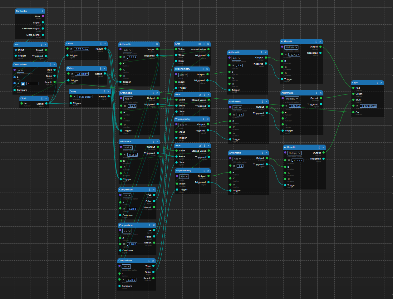
This “psuedocircuit” is an example of a long chain, that will take a while to churn through everything. One component triggers the next, triggers the next, etc. Everything happens one after another. Robust, but slow.

This next circuit parallelizes some of the tasks. The thin arrows are just data, no Trigger Signal is passed along. The Indexes will all start on the first tick, the Math on the second, and the concatenate possibly on the third. With this circuit, if any one of the components doesn’t process right away or in the right order, the concatenate might get bad data. All the branches take 2 ticks to process, potentially leading to race conditions.
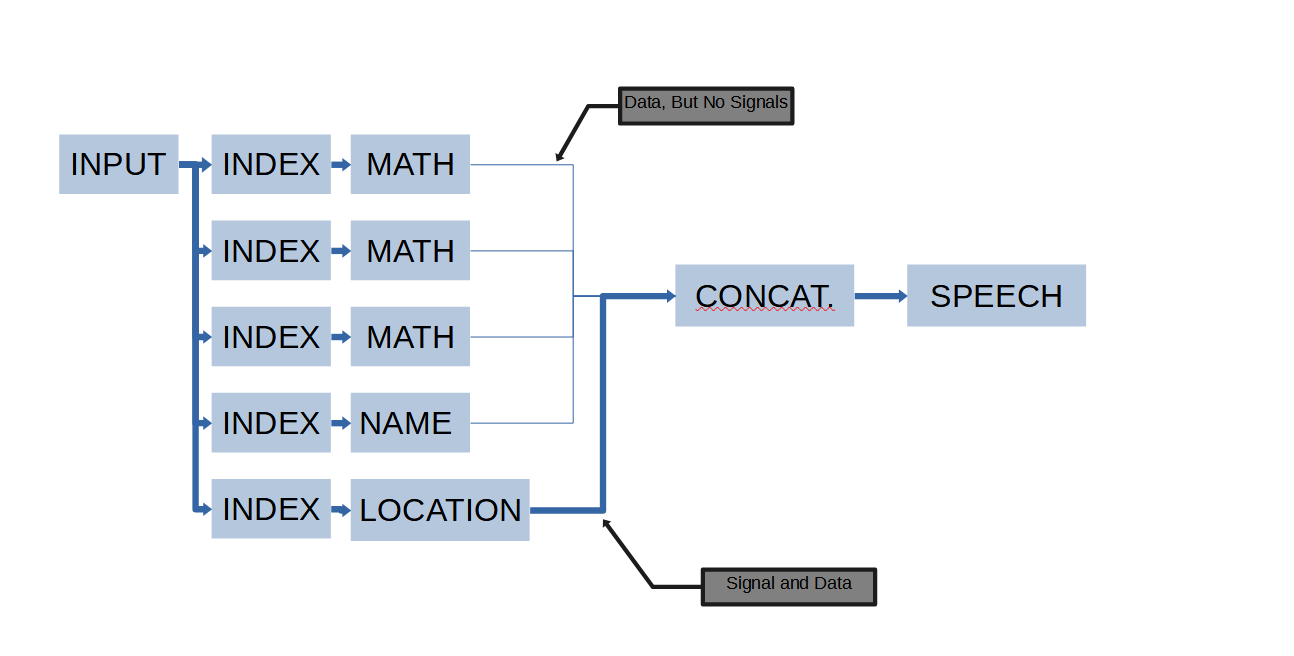
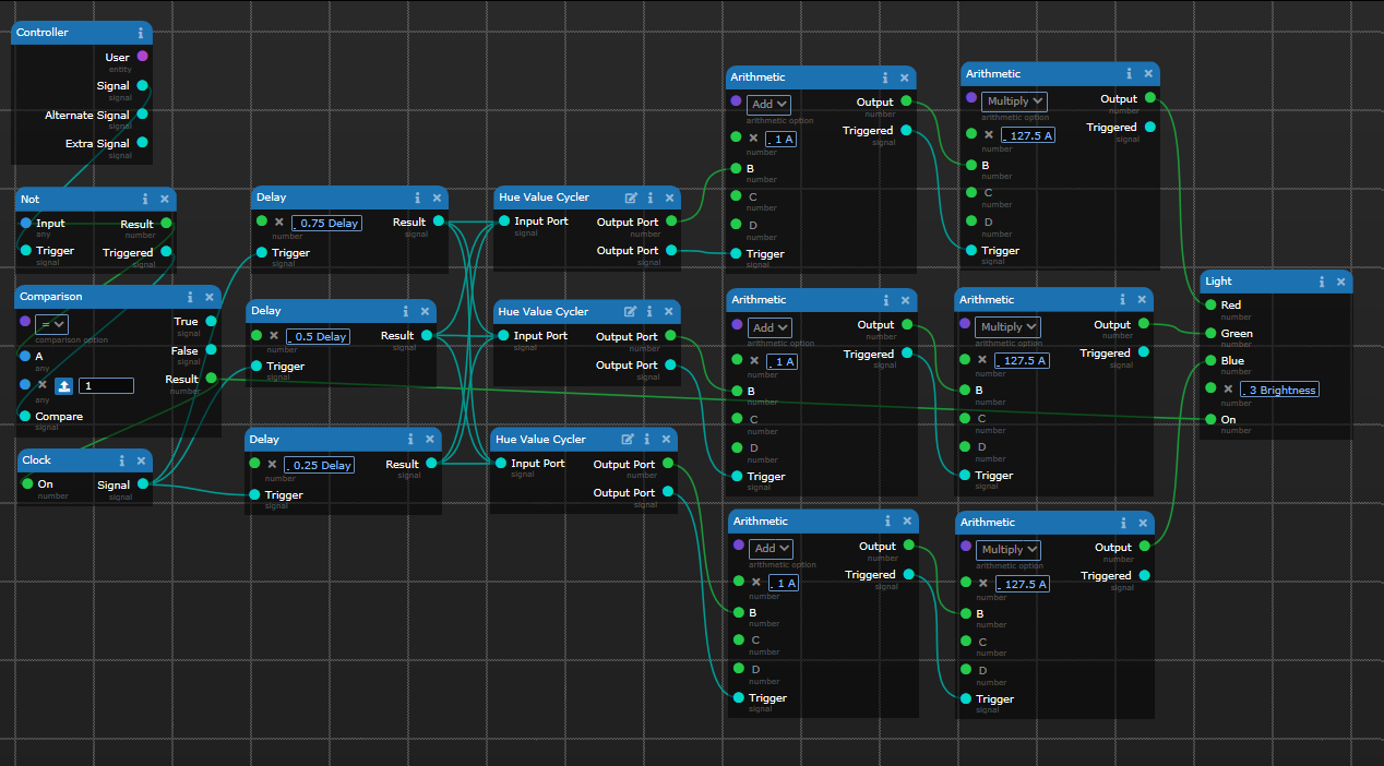
If we simply trigger the final branch off of the second to last branch, we have effectively inserted a two tick delay into when the concatenate runs. The Index → Name has to run first, and then the Index → Location, before the Concatenate can run. We’ve now moved 8 components in parallel, and still given all of the components enough time to synchronize before the concatenate fires, without needing to use a delay circuit.

The first three branches take 2 ticks to run, and the final chain takes 4. This gives us a decent buffer to make sure that everything is executed before we move on to the next portion of code.
Fun USB Connections
Bluespace Launchpads: Automatic Brain Activated Teleporter Network? Send me there.
Crew Monitor Console: Deathrattle announcement system? Got me dead to rights.
Portable Pumps/Canisters: Portable Plasma Floods? Sounds like a blast to me.
This is Version 1 of this Guide. Comments and Questions may be addressed and added to the guide. I may or may not be writing this way too late at night and need to call it good.